It's spring 2020: COVID-19 time. This page follows the progress of the little car up through the start of summer.
Step1. Lighten up.
The old forklift motor.
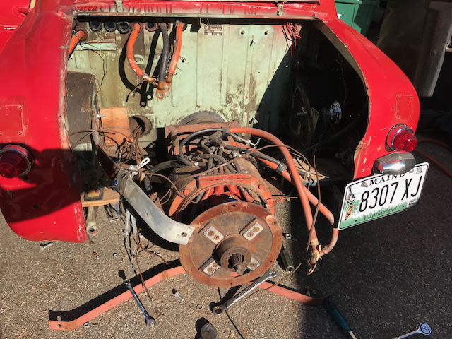
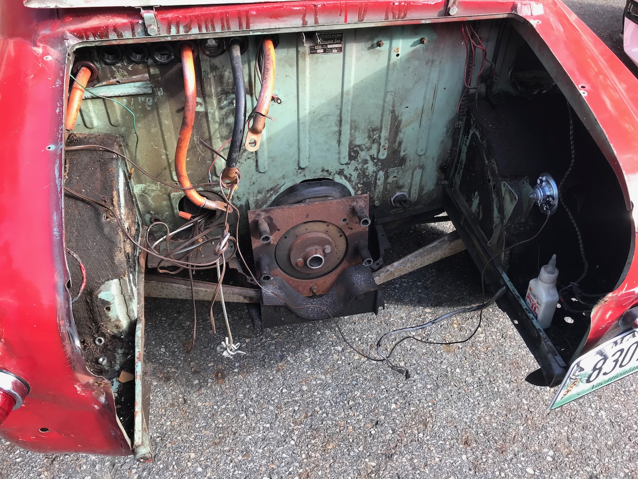
The Vespa 400 comes apart pretty nicely for access to the engine bay. In this pic, I've already removed the rack of relays and the field-weakening resistor coil (and one other relay that did an armature current boost).
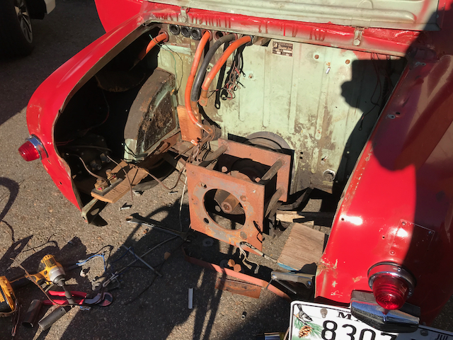
Motor out.
Some pretty simple, but accurate (and that's the thing!) motor adapter work. Shaft reciever had two set screws pinning the key in the keyway, just like anything. Might have been a little longer than it needed to be, hanging that hefty motor farther aft.
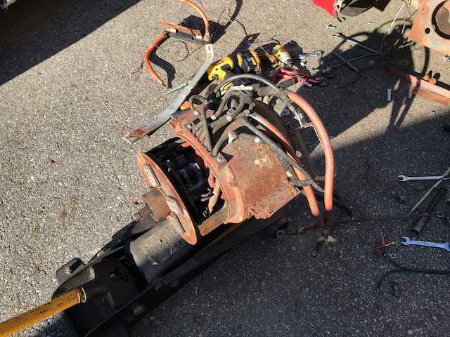
Look at that beast!
Heavy. Heavy, heavy, heavy.
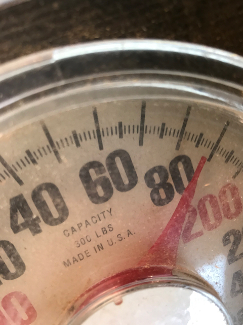
Oh. I see. More than 185 pounds.
That explains why it hurt so much putting it on the scale!
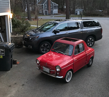
Goodnight, little car.
Nice module of work. Between relays, cabling, and the motor, that's about 200 lbs lighter. New motor will be less than half as heavy.
Step 2. Adapt the adapters, and install a new motor and controller.
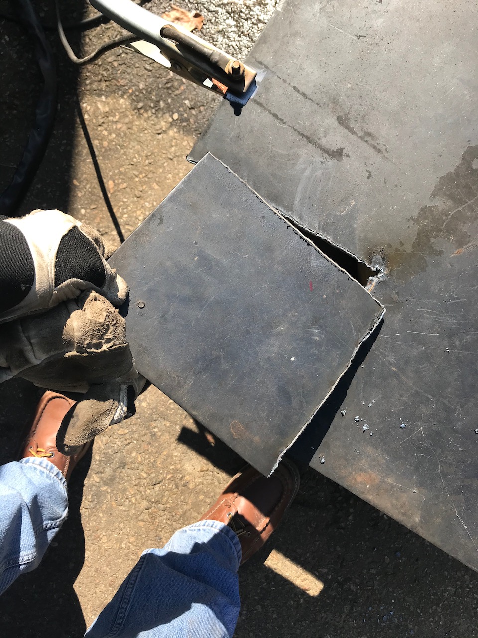
Slab of 1/4" plate after a plasma cut.
This is the blank for the motor mount modification. The existing motor mount is, it seems, the most precise piece of work in the professor's entire conversion (the motor's shaft should be perfectly coaxial to the transmission inpput shaft, and it seems to have been!) , and I mean to leverage that precision.
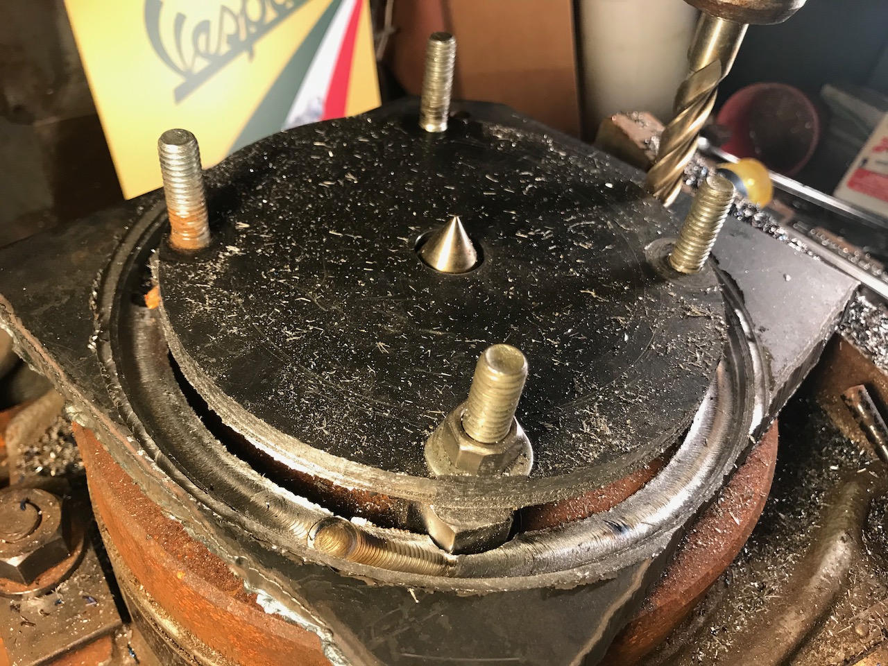
1/4" plate on the rotary axis.
First, make it round... milling machine, rotary stage.
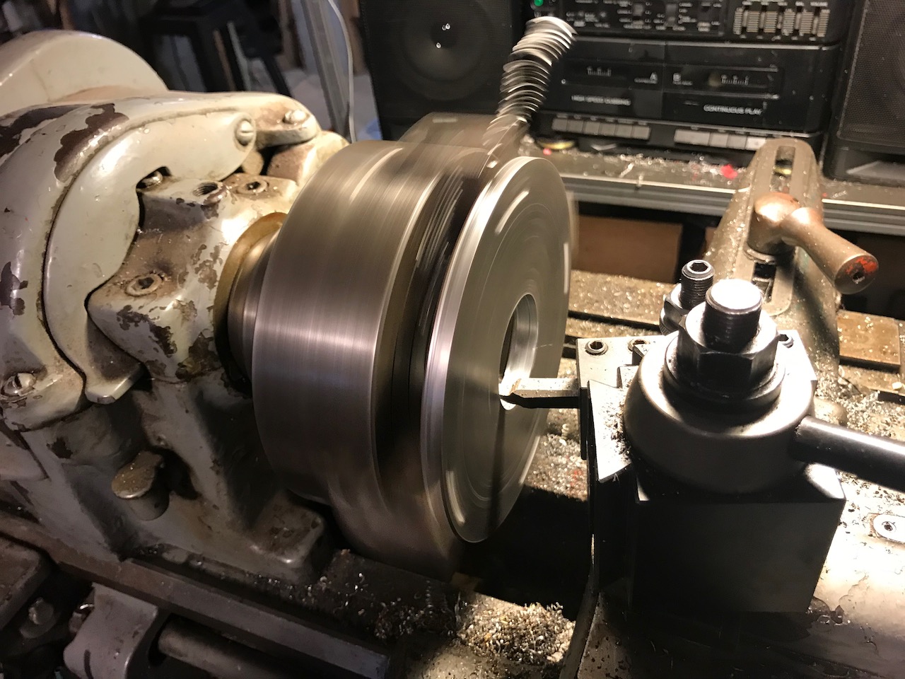
Lathe: center hole to engage the alignment step on the new motor.
Let the chips fly.
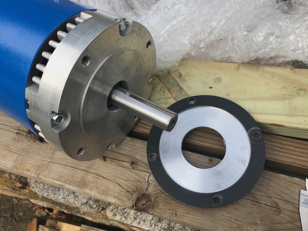
Almost there!
Shiny part is a step in from the dark part to mate with the motor face. The four holes are from machining, and do not matchup withthe mounting holes. The mounting holes, unfortunately, sit on the edge of the disk.
Test fit... looks good!
The outside diameter of this disk matches the inside diameter of the existing motor mount. You can see that the mounting holes for the motor will have to be almost centered on the circumference of the disk!
Motor mount: Four stanchions cut.
The existing mount was two parallel plates, one attached to the transmission face, one to the motor. Motor side is off in this picture.
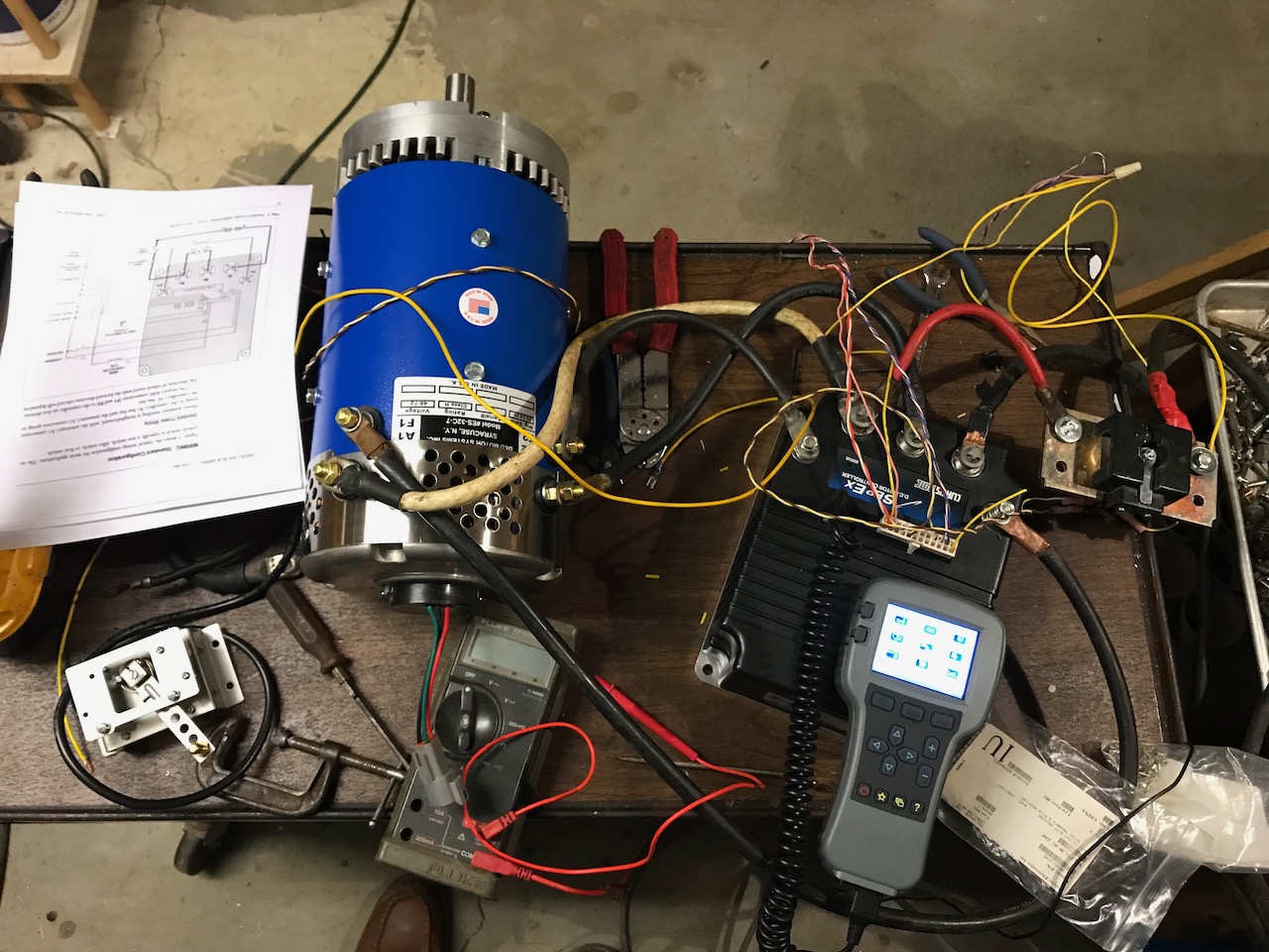
Motor test: The new DC motor and sepex controller on the bench.
This is DC, but with regenerative braking. Most of my EVs in the past have been series-wound DC (like many a golf car, mostly older). This is DC also, but shunt wound, or "seperately excited" (field and armature) and that, with the right controller, will allow regen. Note the hand-held programming module in the bottom right. Curtis controllers accomodate the use of this same device on everything from their three-phase AC controllers to golf-car sized sepex controllers. With it you can configure throttle mapping, current and voltage limits, acceleration rates, etc. And even data logging is possible with one of these!
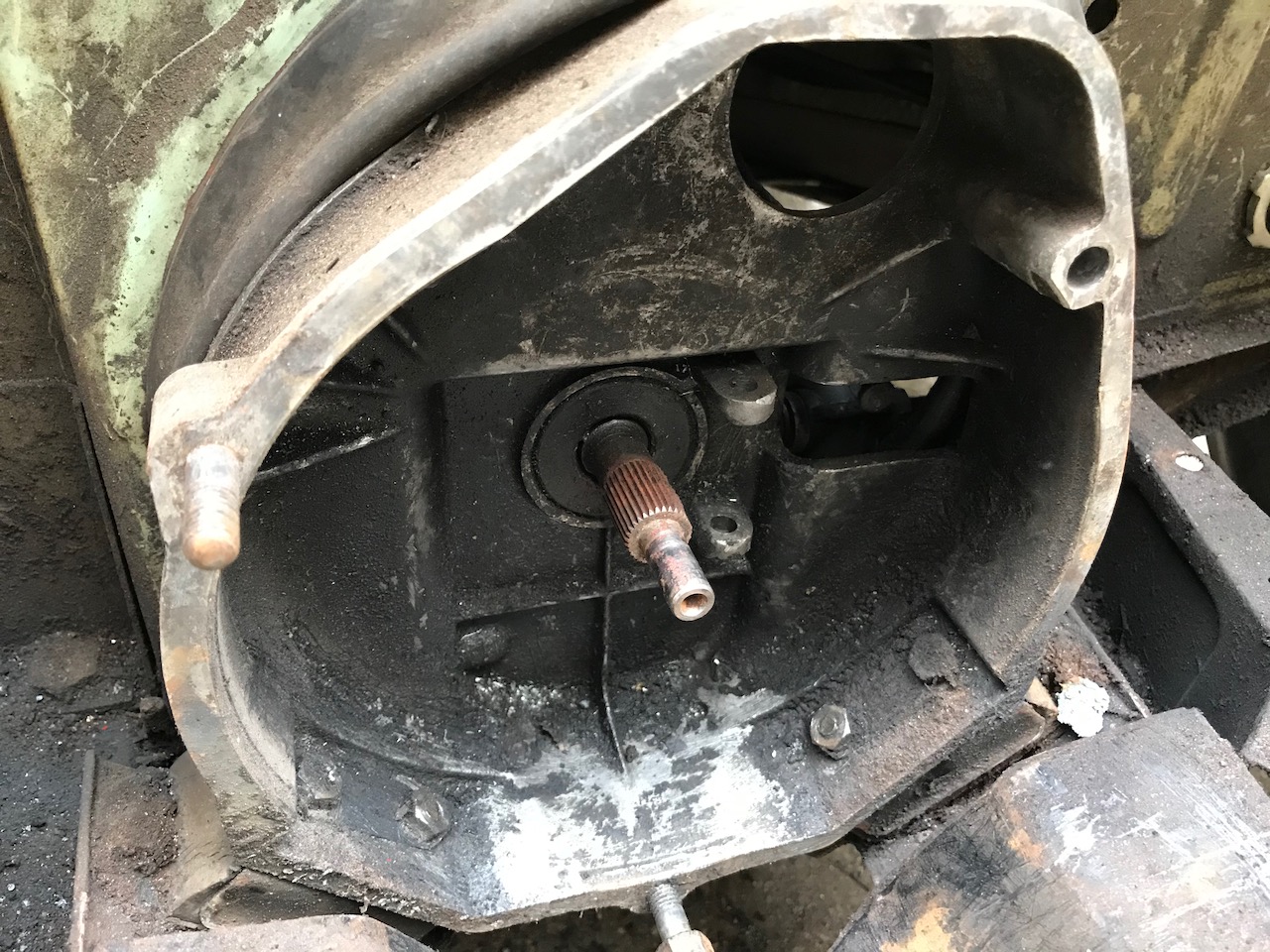
Back to the transmission: The Vespa's own three-speed gearbox input shaft.
I took out the release and throw-out bearing. The pivoted on the lobes by the shaft. The original 19hp two-cylinder two-stroke didn't have much torque... those little shaft splines were good enough!

Back to the transmission: Clutch assembly.
The abuse to the housing is from the unstable fore-and-aft positioning of the assembly as it moved relative to the transmission. Note the release and bearing and forks above.
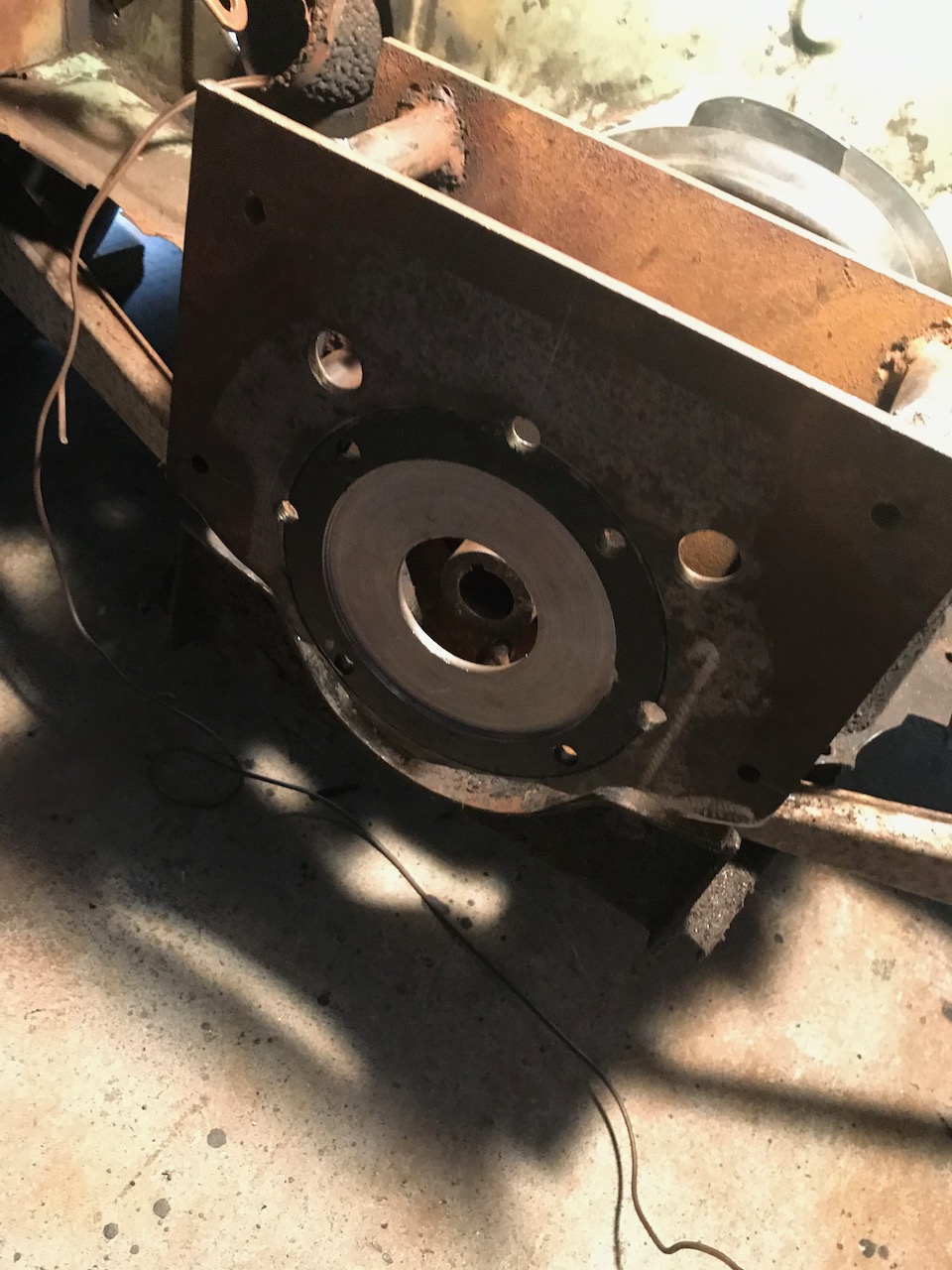
Roughed in: The plates are parallel once again, but closer to each other, and the new adapter disk has been welded in place.
It was a big pain to get the mounting holes drilled: The were half in the old material, half in the new. Used the milling machine.
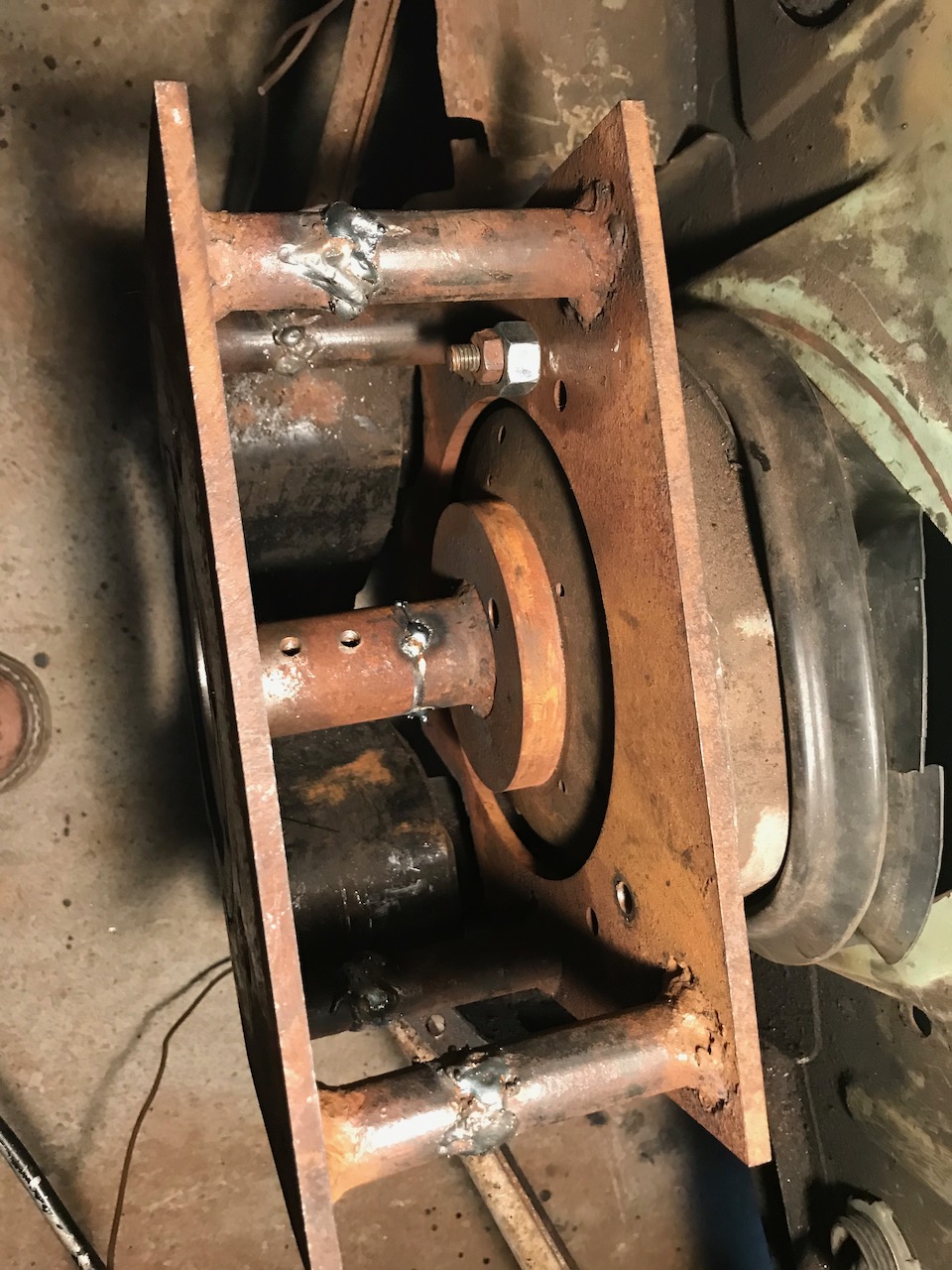
Roughed in: The stanchions are shortened, and the input shaft has been shortened and tacked.
It was easy and worth it to get the plates perfectly parallel.

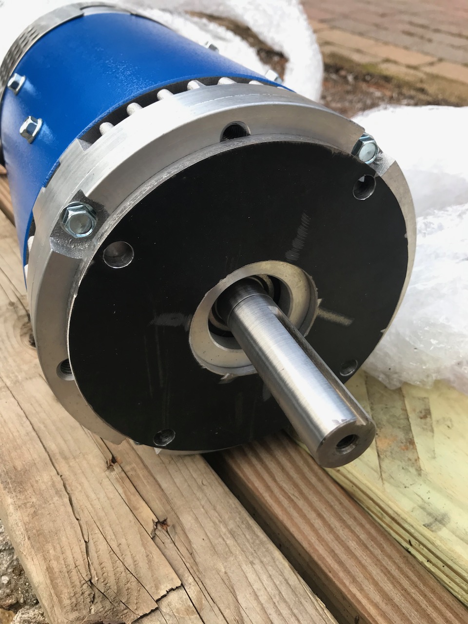
Dry fit: The motor is snug and the shaft alignment seems perfect.
Great contrast: The new motor is 66 lbs compared to the old 185 pounder. Who does't love a factor of three improvement? AND, it's not hanging out as far aft!
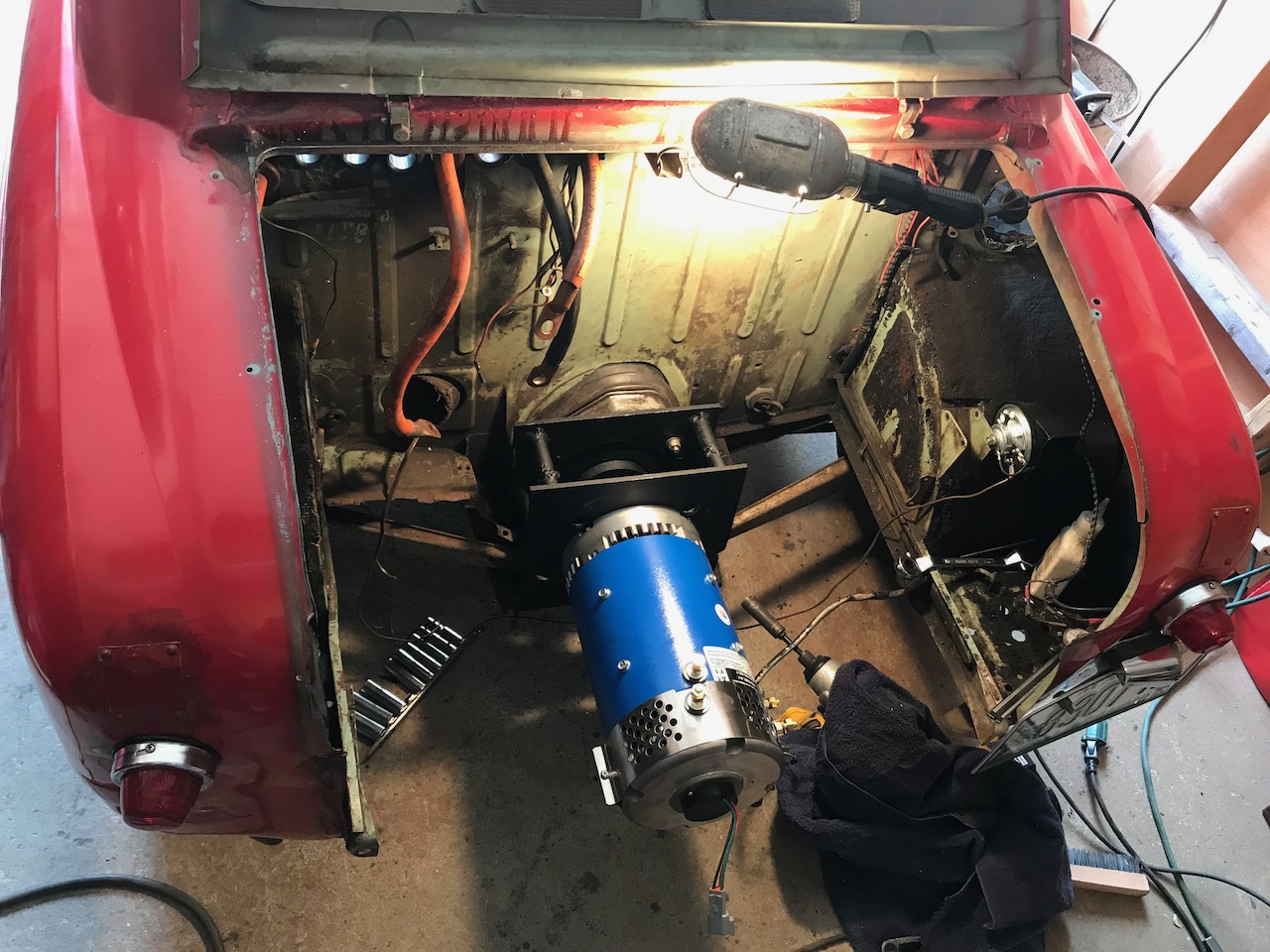
Final fit, I thought: The motor is snug and the parts are painted.
It's going to turn out not to work, but it looked good!
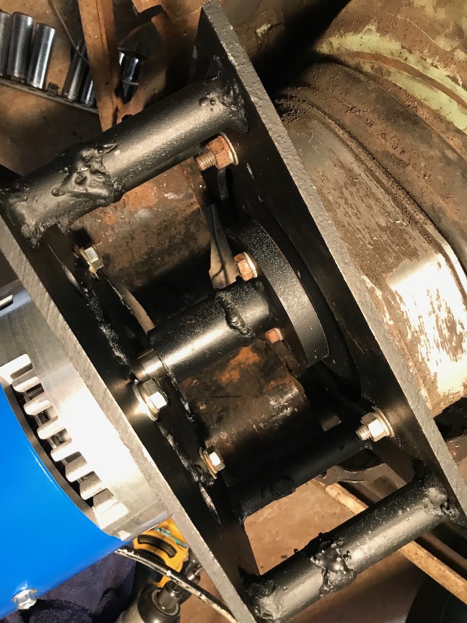
The connection to the clutch assembly is through that beefy spliced shaft.
So clean! Too bad it won't last.
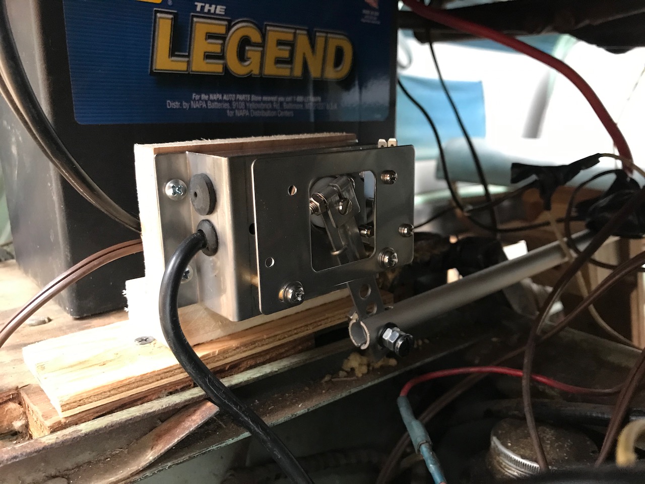
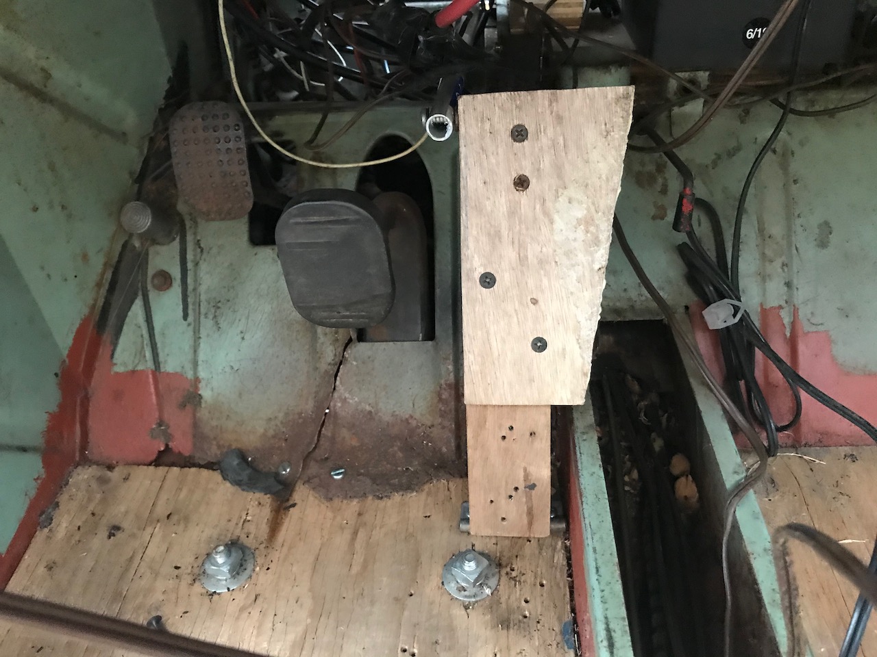
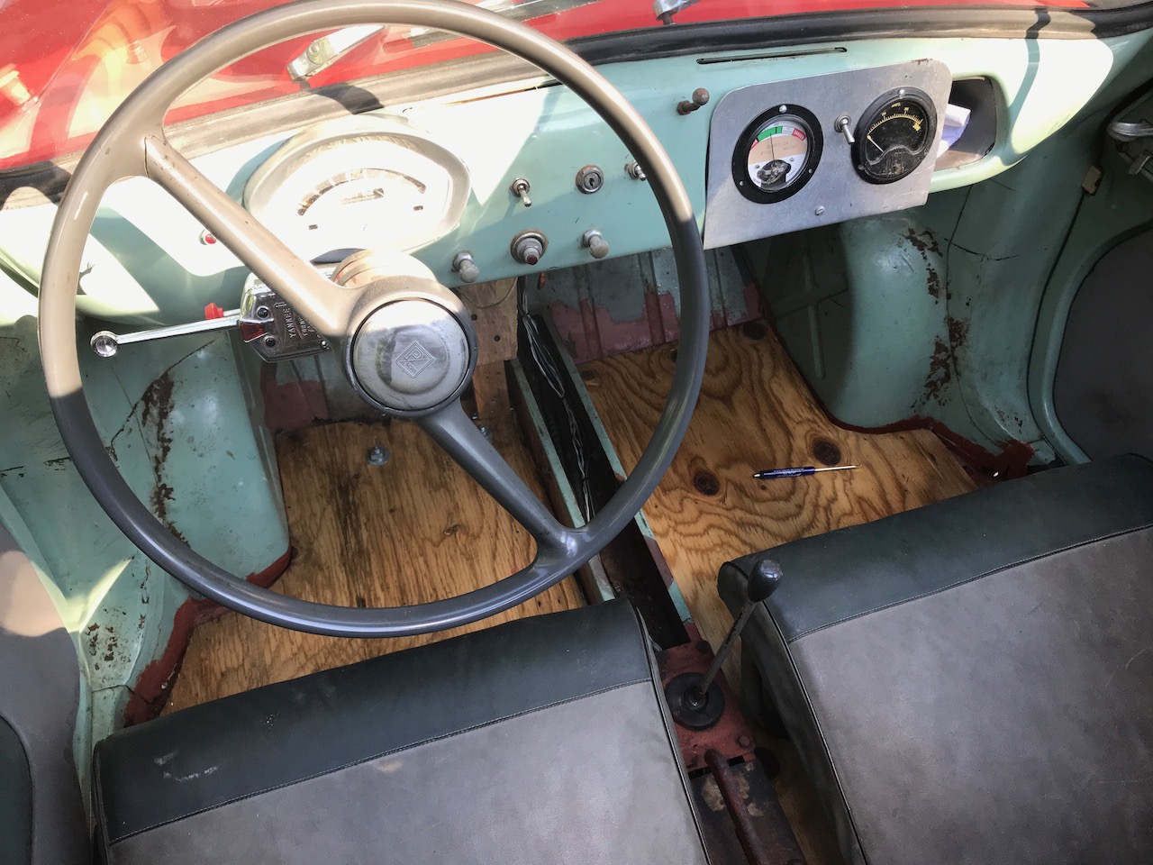
Meanwhile, up front: New throttle.
Getting the spacing right, etc.
Maintaining the plywood aesthetic.
I'm matching the "gas" pedal to the professor's plywood floors.
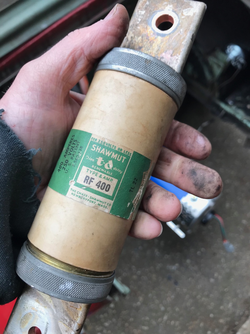
Holding on to history.
This fuse was in the orginal conversion. And it was made in our very own Newburyport, MA. Keeping it!

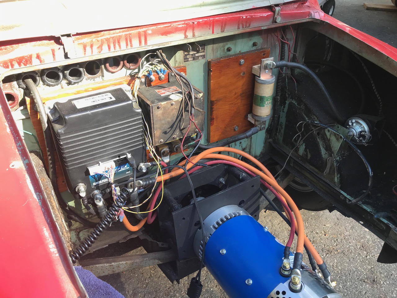
Controller installed, wiring in progress.
There were six navy-surplus relays in the professor's original conversion. I have kept one as the main contactor. It is just to the right of the controller. (Among the programmable features in the controller is the contactor coil voltage. The contactor, like so many things from the military, runs at 28 VDC.)
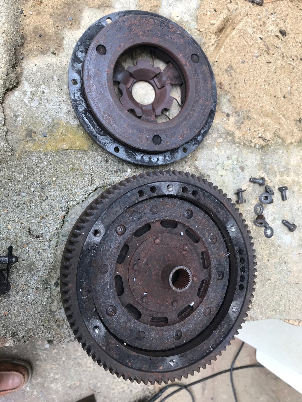
Clutch assembly, opened.
Well. That clutch assembly is eccentric, and giving the car some vibration. It's got to go. I need the clutch disk, though, as it has the splined part to mate to the gearbox input. I discovered that the clutch disk had been screwed to the flywheel by those five round-head socket-cap screws. Good way to prevent slipping, I guess!
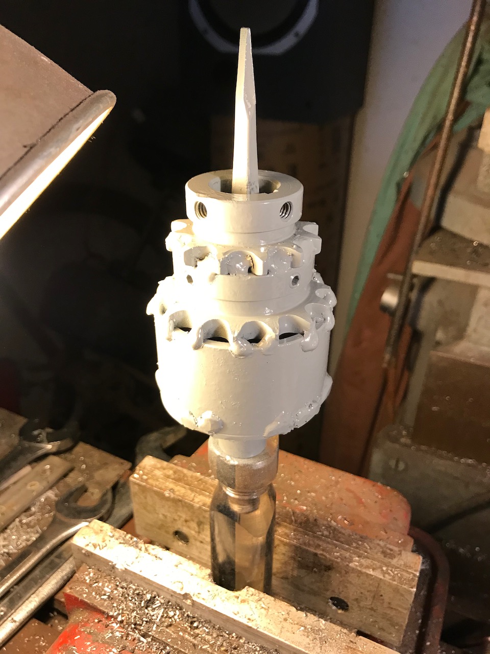
New shaft coupler.
Done up on the lathe for centering, but shown here on a screwdriver for no particular reason. The collar at the top will engage the motor output shaft, the bottom piece is the center part of the clutch disk (with the splines). The wedding cake of sprockets came out of the parts bin.
Step 3. A few other updates.
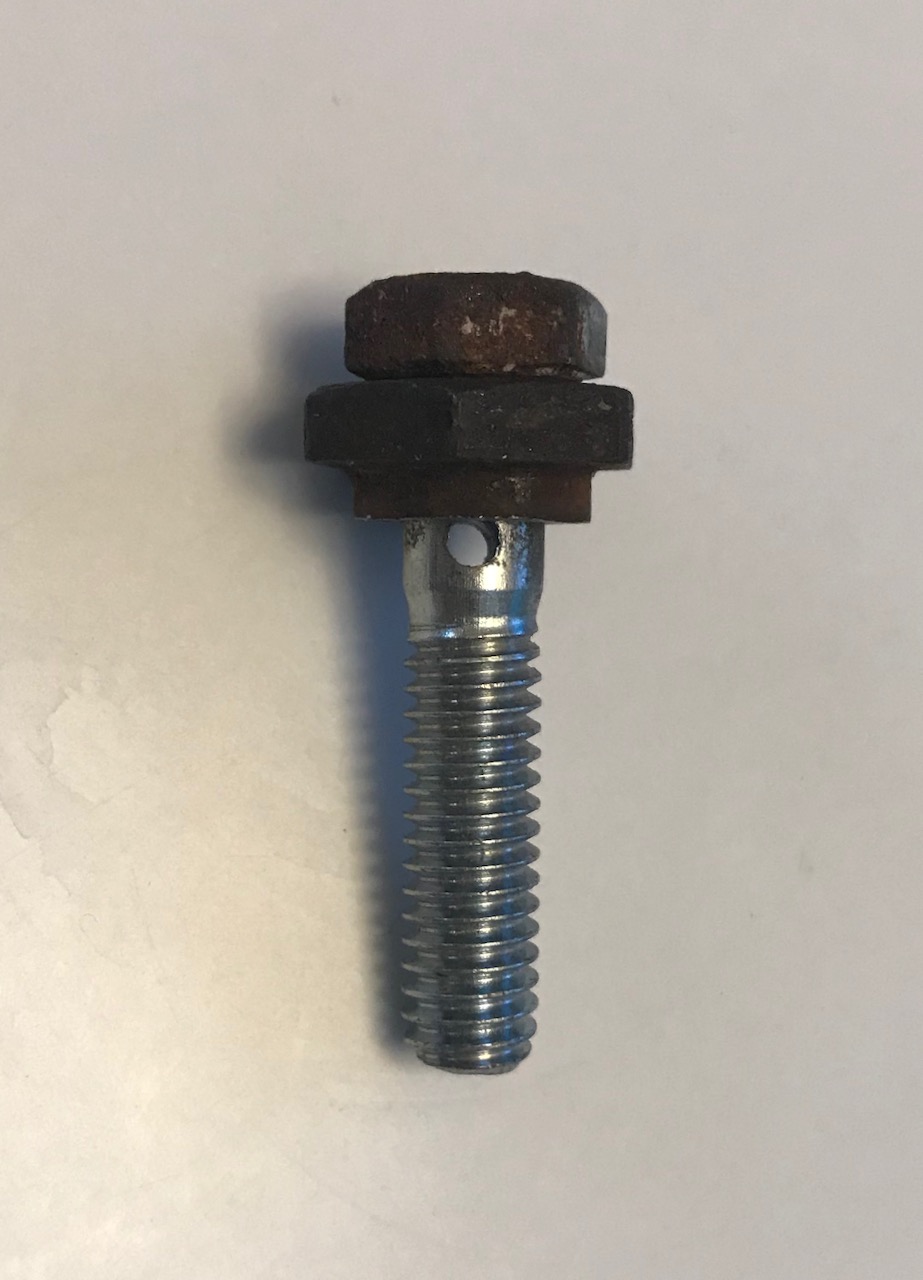
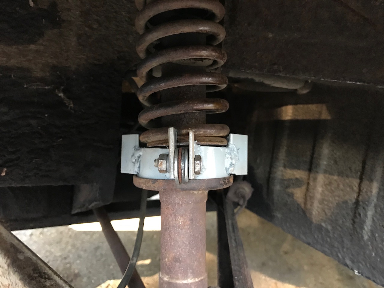
Hacked-together cable clamp for the parking brake, right rear.
The stepped disk at the top is what's left of the original bolt head, cut and drilled. The screw itself is drilled for the parking brake cable to pass through. It took some time to make this... stupidity tax for breaking the original. (Right side came of so easily that I was not cautious when I went after the left.)
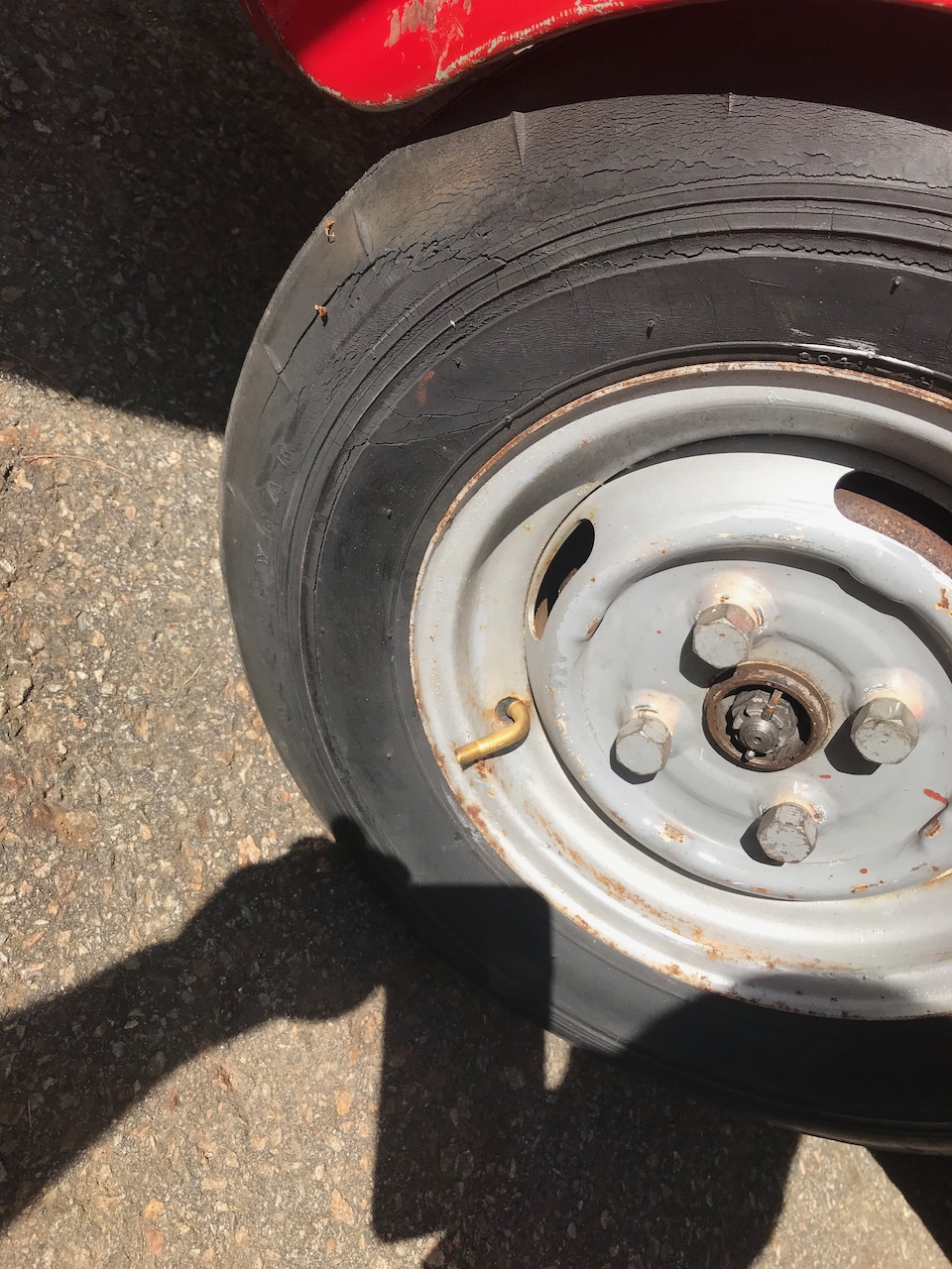
43 years flat; inner tube stem detail.
New tires and rims coming! This is one of the old tires, a 10x4.8 instead of 4.4 (as should be fitted).
1" lifts.
Shed 120 lbs of motor, but I still have about 500lbs of lead-acid batteries in the back. These 1" spacers make the back of the car the same height as the front.
The business end.
How it looks now, including the fuse.
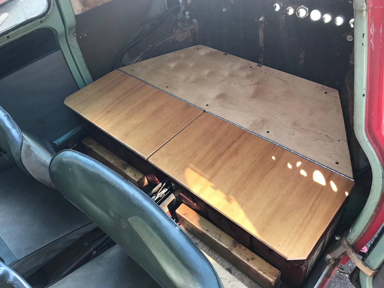
Battery covers.
The plywood aesthetic continues, but with sanding and varnish.
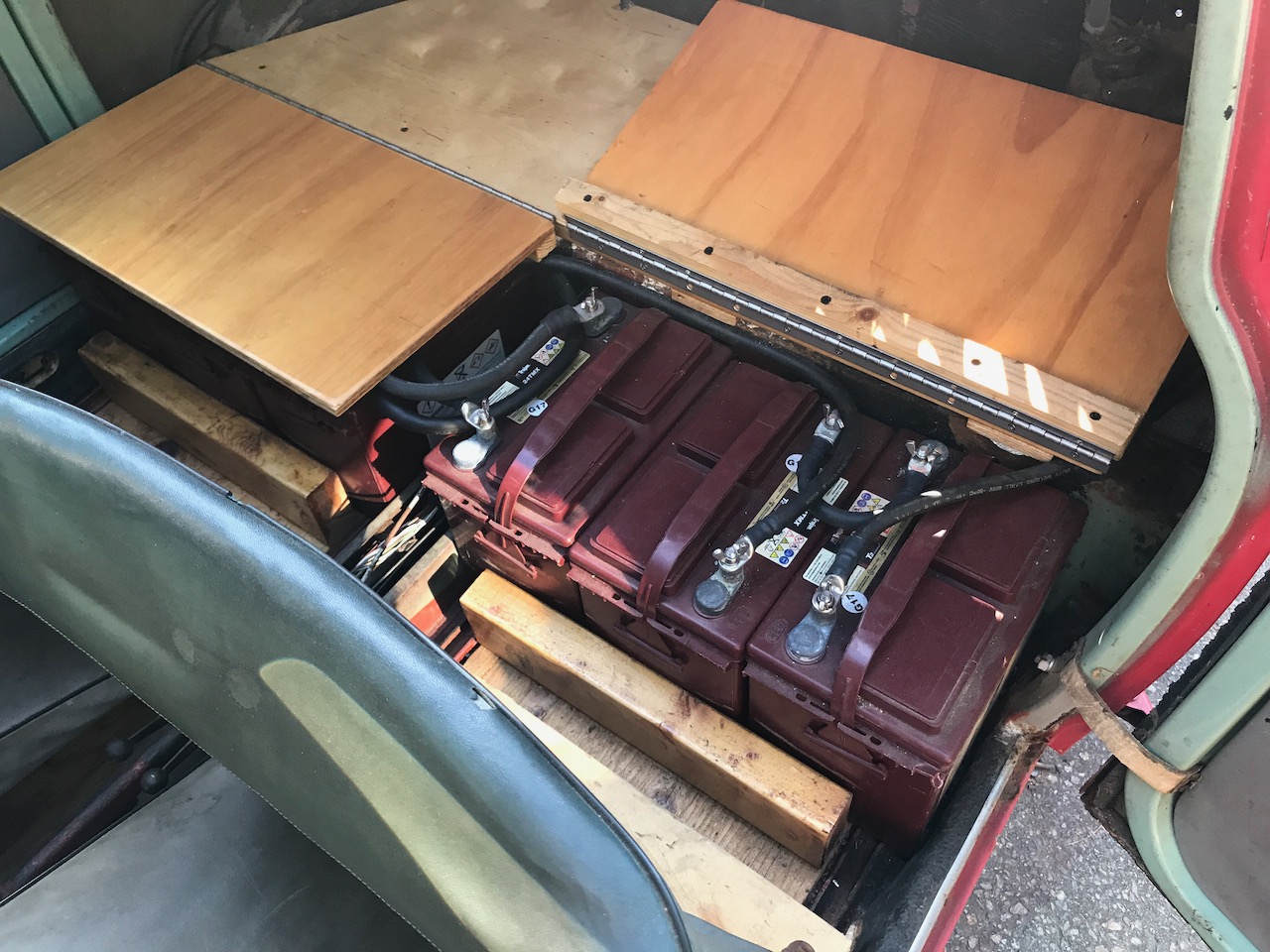
Three of the six batteries.
Each battery stores, nominally, 1.99 kWh of energy.
Refinished floors.
I purchased replacement floor pans from Larry in TN, but I haven't come even close to starting the bodywork required. For now, the professor's plywood stays... but with a quick smoothing and a couple coats of polyurethane.
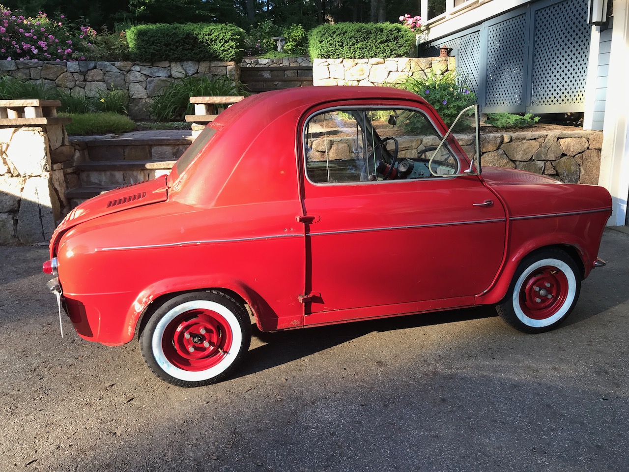
New whitewalls on refinished rims.
I got a new set of rims from Tom and Anna. Wire-wheeled, primed and painted, then off to my local garage for the installation of tubes and tires. Beautiful.
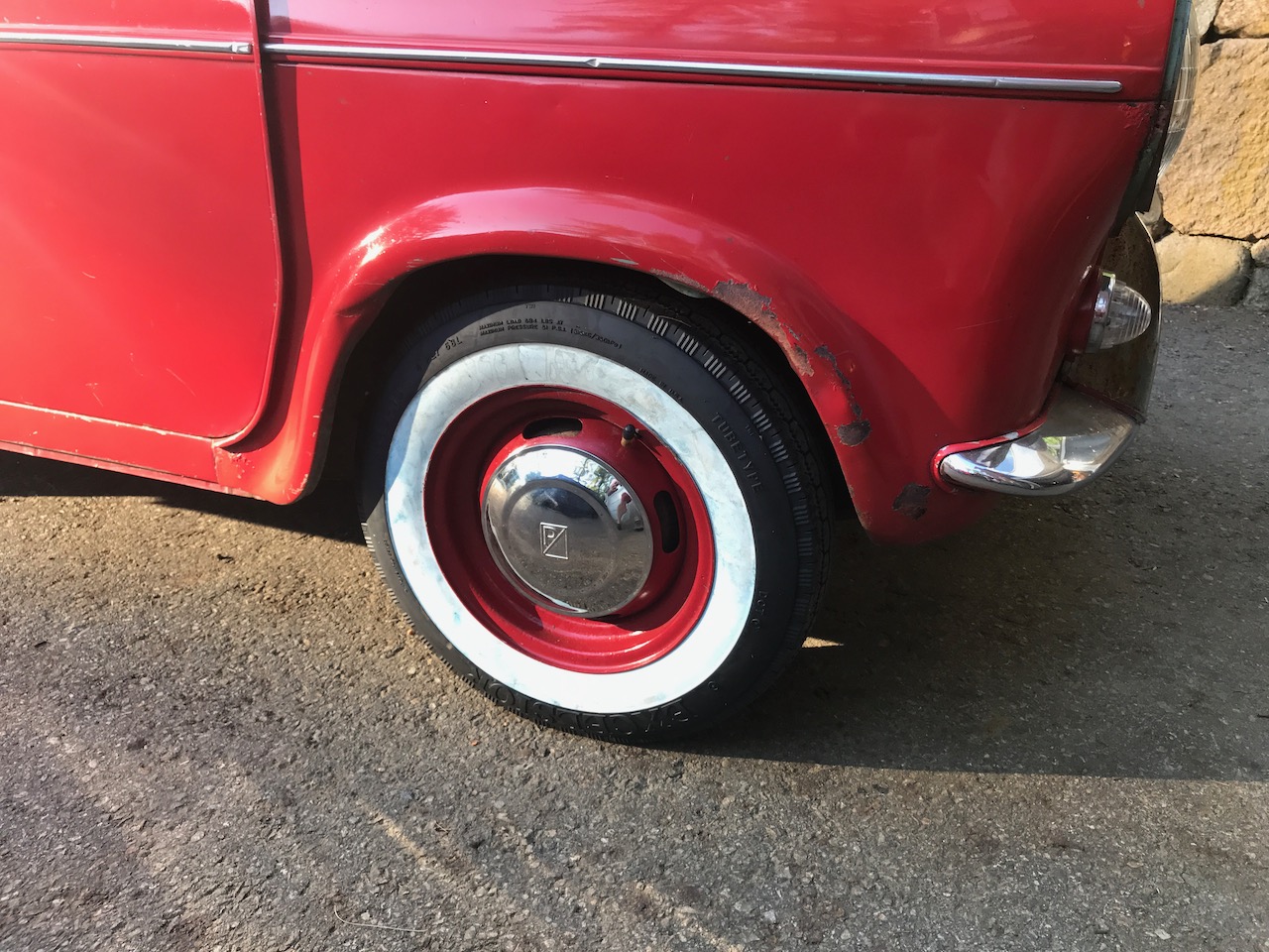
And stainless hubcaps!
Also from Larry in TN, a set of four hubcaps! Larry believes that this particular Vespa was owned by a guy he knows when that guy lived in CT and bought it from a Connecticut dealership. This belief is on the evidence of the peculiar splice in one of the rear half shafts. (Read about it and see it back in Part V.) Pretty cool, if true! There's a "Boston Vespa" sticker visible through the red overspray, too... the other leading contender for origin.
Some range estimating: I took a two-mile neighborhood ride the other day with data loggin running. The sampling interval varies around 0.67s. The simple assumptions that voltage and current are constant during each interval, I calculate that the total energy withdrawn was 0.63 kWhr from the pack, or a little more than 5% of the total available. So: 40 miles for modest driving. I'll get out and do some greater distance at higher speeds soon, get more (and more relevant) data. In short, though, if I were able to get 20-25 miles, I'd be good!
Next chapter: More modernizing: Lithium! Part X