Commutamatic II
Maxion

development log, part seven

in which the hot summer sun sees tilting runs

last updated 8/12/00

Your comments are always welcome. Send me email!


The story resumes now, after a total cost of $2375 and total time of 370 hours, ready to build a proper tilt lock


June 15 and 16, 2000.

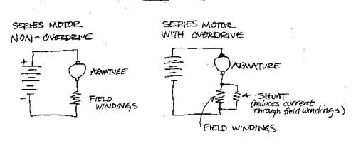
Five more hours, and some interesting experimentation. My father-in-law, who by the way has his EE, told me that by shunting off the field current I would cut the back-EMF increasing the effective voltage, thus raising current, drawing more power, and delivering more power.

Quoting here from an email to my father-in-law...

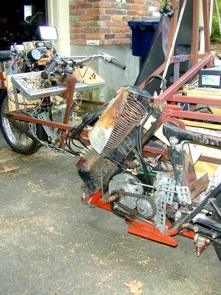
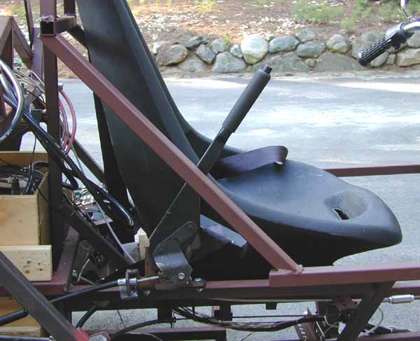
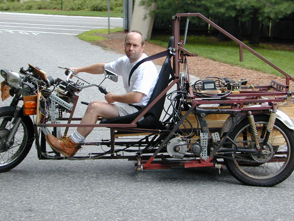
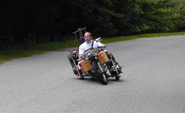
I hung a great big old resistive controller on the frame over the drive motor and connected its two leads to the two terminals of the field windings. I donned my helmet, took to the road.

Having reached top speed, I reached over to the slider and took it from the open-state position, and slid it along the brass contacts, waiting for some subtle seat-of-the-pants difference. I didn't feel anything until the slider went all the way to the fully closed state. (At that moment, then, I had shorted together the field terminals. Given the very low resistance of the field coils paired with the very low resistance of my "short," I probably shunted off something like half the current.) I heard the difference as I felt it, a little whine and a little extra kick. The current reading hopped up about 20%. (Sensible both as a simple circuit consequence, but also in terms of power: no free lunches... more speed means more current had to be drawn at the terminal voltage of the batteries.)

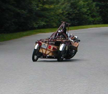
For the first time, the speed of the trike comfortably exceeded 40 mph. Cool. Electric overdrive.

Two other items of note:

  • I tried putting up both of the motors again, going from a 23-tooth sprocket on one-wheel drive to16-tooth sprockets on each of the motors in 2WD. (That's not quite the 2:1 reduction we talked about... I need to order 12-tooth sprockets, if they make them. I may have to diddle the 2nd stage on each side.) The top speed I got was 30, compared to high 30s for the 1WD setup, though the current was lower, correspondingly lower, than the high 30's on 1WD.
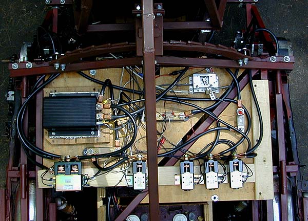
  • The current into the controller is not the same as the current out, though power is (almost exactly, as you might expect). Starting the vehicle up, on the input (battery) side, the voltage stays at terminal voltage of the traction pack and the current rises from next-to-nothing up to, well, high numbers (I've hit 275 A there). Meanwhile, on the output (motor) side, the current will hit the 275A limit and hold there as the voltage climbs from next-to-nothing up to terminal voltage of the traction pack, then fall back (unless I am pulling a hill).

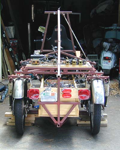
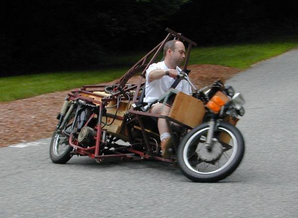
The resistive controller is an experimenter's friend. I have used the resistive controller from one of the donor golf carts for many experiments; indeed, it was THE controller when I got the Maxion inspected its first time. Here it is in place as a variable resistor for the field winding bypass.

Total cost so far: $2375. Total time so far: 375 hours.


June 17 to July 3, 2000.

25 more hours, and $10 for a emergency brake lever and $30 for an emergency brake cable, plus $15 for a set of brake pads. It took a longer time than I expected, but it is a fairly complex fabrication and a precise structure. I made the arch by cutting 14" x 2" plate steel in lengths with 9 degree cuts on each end. By butting them end-to-end, welding them up and grinding them smooth, the straight segments approximates a part of a circle.

The tilt lock, clamp assembly. The cable (top left) closes the pads (bottom center) against the two sides of the 1/4" thick x 2" wide arch. Note the return springs, pulling toward the rear of the vehicle to open the pads.

The tilt lock, full view. The full span of the arch is visible. It behaves like a disk rotor on a car's brake assembly. The shiny part shows the 45 degree sweep to each side of vertical.

The tilt lock, ratchet lever. The lever (pointing almost skyward) is at the driver's right hip. Pulling up on the lever engages the tilt lock. This lever came out of a Chevy Citation, I think. It was a couple of weeks ago that I found it down at Rich's Auto Parts. (Thanks, John!)

Total cost so far: $2420. Total time so far: 400 hours.


July 3, 2000. Red Letter Day!

Tilting runs!

By the end of the day of running with the tilt lock disengaged, I was throwing the trike over from limit to limit, doing as sharp turns as the Maxion can. Fun.(Understatement.)


July 4 to July 7, 2000.

10 more hours, and $450 worth of new contactors and switches. With the switches, the driver can choose series, parallel, or individual motors, and direction (of left motor only). Expensive, but wow is it cool to be able to work the motors any way you want.

Indeed, I have two "gears" now. I start out with both motors in series; I get high current and full voltage out of the controller right away. Then, by switching to parallel mode, I get even higher current (same top voltage) for maximum speed of 40 mph.

Motor selection, driver's view. The four switches at the center of the handlebars controls motors. You can run either motor by itself, both motors in parallel, both motors in series, or the left motor by itself in reverse. It also adds a measure of security, since correct positions are simply not labeled.


Motor selection, bird's-eye view. The control deck behind the drivers's seat has on it the pulse-width modulation controller (black box, left) reversing contactors (bottom left), and a row of four contactors for choosing parallel or series modes.

Total cost so far: $2870. Total time so far: 410 hours.


July 7, 2000. Red Letter Day!

The Maxion passes inspection. ($15) And here we are on the eve of the Microcar and Minicar Classic. Imagine that! (Total cost becomes $3305.)


July 8, 2000.

Saturday night I couldn't get to sleep. It was Microcar Day, and I was still all jazzed up. In the following, excerpted and edited from an email to Dick Slade, a wise man and occasional consultant to my silliness, is a description of my new tilt lock vision.

RATCHET is the word, allrighty!

I was having a hard time getting to sleep on Saturday night, and as I lay awake I was reviewing my frictional brake critically. It has one disign deficiency (it can't hold the thing from flopping, at a standstill, past about 25 or 30 degrees of lean), and a it has a practical (and perhaps safety) deficiency, that it takes arm strength to apply, and from an arm that belongs on the handlebar!

In a flash, and I mean it, about a 10 minute start-to-finish fast-forward design job in my head, I saw it; a spring in/spring out design. You apply it either by handbrake lever (for parking) or by the pedal I already built for the job (for, say, wiating at a light). All either of these does is apply tension to a spring which makes a pawl apply to a large-radius ratchet. (Picture the current steel arch but with steps on it... steps that lead to a slot in the top-dead-center.)

By applying it, you at least can't flop any forther to the outside, OR, if you keep wigglin', it finds center and latches!

Then, upon release of lever of pedal, there is spring tension to remove the pawl. Of course it can't if it's "loaded", but as you drive and find a neutral position, it pops free, and off you go!

At Microcar Day: two tilters side-by-side. A guy named Steve cam with his home-built tilter. It has one wheel that leans (front) and a former Subaru front end that doesn't. Big day, seeing two tilters side-by-side!


July 9-17, 2000.

Five more hours, and $15 for more steel. (1" x 1/4"). Add teeth to my steel arch. Fabricate pawl assembly. Test it standing still (no springs yet, no attachment to pedal or cable). Works like a charm.

Total cost so far: $2900. Total time so far: 415 hours.


July 18-24, 2000.

Ten more hours, and $10 in miscellaneous parts. Finish connections from hand lever and from pedal to the tilt lock Strighten rear wheels (they got canted in a little).

The tilt lock, mark II. The spring, visible above, removes the pawl from the ratchet whenever the downward tension from either the hand laver or the pedal is relaxed. The springs below go to the pedal and the hand lever. If either the pedal or the lever is applied, downward spring tension pulls the pawl into the nearest low spot. This way, the vehicle can alwys tip more toward "straight up," but never away, when the lock is applied.

Squarer back end. The trailing arms on the donor cycles' back wheels were not designed to withstand strong lateral forces. Sometimes lateral fores were applied, and hard, when the bushings came out of the tilt mechanism, for instance, and the rear segments were not parallel. I straightened them up, and I think I might have to beef them up someday, too. I'll wait to see whether better alignment protects them from geeking again.

Total cost so far: $2910. Total time so far: 425 hours.


July 25 to August 10, 2000.

No time actually spent working on the trike, but since Slim was visiting, it was time for taking some pictures.

Turning with the lock engaged. It works like a charm.

Hard left. This turn was a success, despite the proximity to the trees!

Medium-hard right. Poetry in motion.

Zig-zagging down the street. This is a pretty hard left; angle of lean says so.

Turning in the width of the street. At speed, no less.

Finishing the turn within the width of the street. Room to spare.


And yet, 
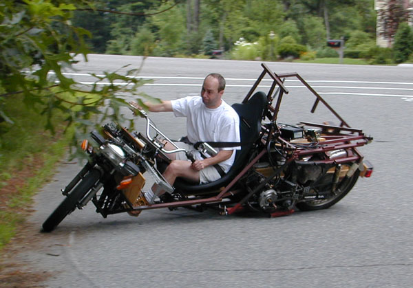
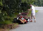
the perpetual problem... Dynamic stability requires friction. At the edge of the trees, I lost that friction in the pine duff, and skidded to a stop. My heel and calf got banged up. It's sobering and scary, even at slow speeds on a side street, to come a-cropper. It's time to tighten up for the fall.


Fall is coming, frivolity must give way to some more seriousness. It's time for a new chapter... Maxion Log, Part Eight.


Back to Back to Max Hall's homepage.

Back to Maxion table of contents.

More information about the nifty kin of the Maxion can be found at the Tilting Three-Wheelers home page.
Send me email!